90 Degree 24 pin connector

Karder

Limp Gawd
Joined
Jul 9, 2012
Messages
377
Has any one ever tried making their own 90 degree 24pin adapter?

I don't mean these ones you can buy at different stores.

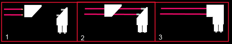
I'm talking about taking a 24 pin extension, using just the heads and somehow connect them.
So it could be used on any board, without soldering (will require soldering while making it, though).

I am planning on making one, and just wanted to see if anyone had some input.

I can add that I am about to finish a 90 molex connector (female to male) that turned out better than I expected. Only issue is painting it. Will post pictures soon.
 
Hmm....

Probably the best way to do that is to get a blank connector, cutting much of the top part off so that you that you have just enough for the clip, and then custom making some sort of cap to put on top after you have installed the wires to force it into a 90 degree angle.
 
I was planning on cutting each of them at an 45 degree angle, solder some pins (female and male and make sure they have correct lengths) together and bend them 90 degrees.

Then, when you insert all the pins into one part, you can just slide over the other part and use something like J B Weld to attach them.
 
I've though about making one of these several times. I stopped when I realized that a 90° adapter may cause broken pins on the ATX connection over time as I'm messing around in the case because of the mechanical leverage the 90° connector places on the ATX connector on the board.

Clarifying my post by stating the design of an adapter like that is not inherently bad, just saying that "I" would undoubtedly end up breaking the connector since I tend to be rougher than I should when futzing around in the case.
 
Last edited:
I've though about making one of these several times. I stopped when I realized that a 90° adapter may cause broken pins on the ATX connection over time as I'm messing around in the case because of the mechanical leverage the 90° connector places on the ATX connector on the board.

Clarifying my post by stating the design of an adapter like that is not inherently bad, just saying that "I" would undoubtedly end up breaking the connector since I tend to be rougher than I should when futzing around in the case.

Understand the worries. Although, mine will be built entirely outside the case. When done, I'll plug the cable into it and then plug into the motherboard.

So in the end, it will be like plugging a regular cable into the motherboard
 
Use a few 90 degree pieces of 2mm copper bar stock. Snip with tin snips.
Place either 1cm or 1.5cm pieces in each pin and solder, so there are staggered connectors (left side of the connector will be .5cm higher. Solder on your 14g wires and heatshrink into the connector. Place connector lightly (about 30% of the total possible insertion depth) Into your mobo to align the pins. Fill a 10ml syringe with 5m epoxy and fill each connector square carefully, which is why we didn't insert the connector fully.

Use epoxy resin for a clear fill of the connector. Depending on heatshrink and connector colour, filling with clear resin would be very pretty, more so if you dyed it.
 
I started the project yesterday.

Some background, I want to create that 90 degree 24 min connector that does not exist.
I have three main requirements:

1. It can't be too bulky
2. It must be simple to use and require no modding to anything (once done)
3. It must look decent and uniform. Preferably black in color.


So here is what I managed yesterday. Forgive me for not taking better pictures, but using my phone and just wanted to share some. Also, the pieces are not completely cleaned yet, as I am still in testing phase.

I cut up the pieces in about 45 degree angles


I then inserted 2 pins, as pictured above and below, that I had just clamped together and bent by 90 degrees


The goal is to somehow insert all 24 pins and be able to attach the pieces together like this.


So far, I have come to these conclusions:

1. It is very delicate work
2. You see how the pieces have a lower and an upper level row? You have to make sure that the pins that you have attached together are almost exactly the same length. Lower row are a bit shorter, obviously and the upper row pins need to be a bit longer. My margin of error is around +/- 1mm per row.
3. It is difficult to sand and cut plastic. Really difficult to get smooth edges.
4. Once the pins are made and bent by 90 degrees, they lose some structural strength. This makes it difficult to attach the plastic pieses together as the pins are prone to bending. That is why they all must be very uniform.


Hopefully I will pick up some bare copper wire and see if I'll be able to attach the pins together with the copper wire, and instead bend the wire. The goal with that is to maintain the structural integrity of the pins. The challenge with this is that I would have to cut off part of the pins, or they would be too long, especially on the lower row.

That's all for now
 
Last edited:
Use a few 90 degree pieces of 2mm copper bar stock. Snip with tin snips.
Place either 1cm or 1.5cm pieces in each pin and solder, so there are staggered connectors (left side of the connector will be .5cm higher. Solder on your 14g wires and heatshrink into the connector. Place connector lightly (about 30% of the total possible insertion depth) Into your mobo to align the pins. Fill a 10ml syringe with 5m epoxy and fill each connector square carefully, which is why we didn't insert the connector fully.

Use epoxy resin for a clear fill of the connector. Depending on heatshrink and connector colour, filling with clear resin would be very pretty, more so if you dyed it.

Great idea! I will definitely be looking at this solution
 
Why not run all the wires through the big piece first, solder the wires to the pins, and then epoxy the two pieces together? That way you're not trying to monkey around with trying to connect wires inside the piece, it'll be out in the open where it's easily accessible.
 
Why not run all the wires through the big piece first, solder the wires to the pins, and then epoxy the two pieces together? That way you're not trying to monkey around with trying to connect wires inside the piece, it'll be out in the open where it's easily accessible.

I'm not sure I understand what you mean. I am not planning on using long wires. Max 1cm pieces.
 
I'm not sure I understand what you mean. I am not planning on using long wires. Max 1cm pieces.

I think Tsumi had the same idea that ran through my head while reading through this thread.
He means the part you cut off, run the 24 wires through it first, then connect them to the part that will plug into the board. Then you could glue the 2 plug pieces back together.


Work is a little slow, so I made up this little pic for you.

1.Run wires through upper connector 2.Connect wires to pins on lower connector 3.Glue connector back together
90DegreeATX.jpg
 
Last edited:
I think Tsumi had the same idea that ran through my head while reading through this thread.
He means the part you cut off, run the 24 wires through it first, then connect them to the part that will plug into the board. Then you could glue the 2 plug pieces back together.


Work is a little slow, so I made up this little pic for you.

1.Run wires through upper connector 2.Connect wires to pins on lower connector 3.Glue connector back together
90DegreeATX.jpg

Dang, that's a good picture! Thanks.

But still not what I hope to achieve. My hope is to to this, but with a 24 pin connector. This one is just a molex I did, haven't painted it properly yet. This way, you can connect any other 24 pin power cable to it.


If I do your version, it is difficult getting the other pins in there instead of the cables. I hope you know what I mean
 
Ah, I get what you want now. In short, it's just a 90 degree adapter with no wires attached.

If you're running a case with space behind the motherboard for the cables, I would just simply make an extension, and run it behind the motherboard and connect it there. Seems like that would be far simpler.

Simpler indeed, but simple is not my middle name. Nor is advanced, now that I think of it :p

My main goal is to have an adapter that I can be used in almost any build and look decent in all of them. And that bend of cables always by the motherboard bugs the living mosquitoes out of me!
 
I did it! (kind of)

Picture below shows the unit just before I glued with epoxy and shut close. It's not pretty, pins are uneven lengths, but it's getting close now


Now here is my problem, when I unplugged my 24pin from the motherboard, plugged in the new 90 degree connector and then plugged in the 24pin power again, something happened.

My computer turns on, all fans are running, lights are all no BUT my monitor does not get any signal.

I will try resetting the BIOS by removing CMOS battery for a while when I get home from work.
But if that isn't the issue, anyone got a clue what it might be?

I am so close now, don't want to give up.


EDIT, there is no going back now, because it's glued together. Also, it's difficult enough removing one pin at the time, but removing 24 pins at once is impossible.
 
Kind of sounds like a pin or two may not be getting a good connection.......may be a bit hard to test.....I'd maybe try wiggling the cables a bit to see if you can get it to boot up.

The first time I ever sleeved a 24pin I used an extension cable so I wouldn't void my PSU warranty. I tried to remove the pins from the connector and reuse them in the same connector, and it caused some strange issues. Turned out some of the pins were really loose in the plug and weren't making good connections.
 
I doubt it's the connection, because the old cable I used before testing this 90 degree one now gives me the same error.

I am fearing something has broken, but want to hold off on that fear until I am 100% sure
 
I wished all of this was current with motherboard makers now. All the straight up plugs are old. It is 2013 fixing to be 2014 and we still don't have all right angle connections on boards. Worst thing to see if all the connections sticking up on a board. Good luck to you on your testing.
 
I wished all of this was current with motherboard makers now. All the straight up plugs are old. It is 2013 fixing to be 2014 and we still don't have all right angle connections on boards. Worst thing to see if all the connections sticking up on a board. Good luck to you on your testing.

Correction! We do have one (prototype)! It's currently inserted into the computer I am using to computer I'm typing this on. Very lightly inserted.

Granted, it is still ugly, but hey it works.

i solved my previous issue with the black display by removing the CMOS battery and the PSU power cable for a mere 60 seconds and it was fixed. Just had to re-apply my CPU overclock and we're running.

Next step is to sand, paint and re-route my 24pin cable and we are all good.

Maybe sell my idea to someone :p

 
Back
Top