Updated with Crappy Photo Guide Tour
I thought I would post about something I fixed last week.
So, while I was at work, my wife needed a power outlet, so she unplugged my Klipsch 4.1 speakers from the surge protector (not the V2.400 version, but the newer revision that Klipsch made right after that. all this is applicable to both though, as all klipsch really changed was the crossover points for the satellites).
Long story short- wasn't muted, so when she plugged it back it- speakers no worky no more.
These aren't the best speakers, but for casual computer music and gaming use, they're great (and I've had them for a pretty long time).
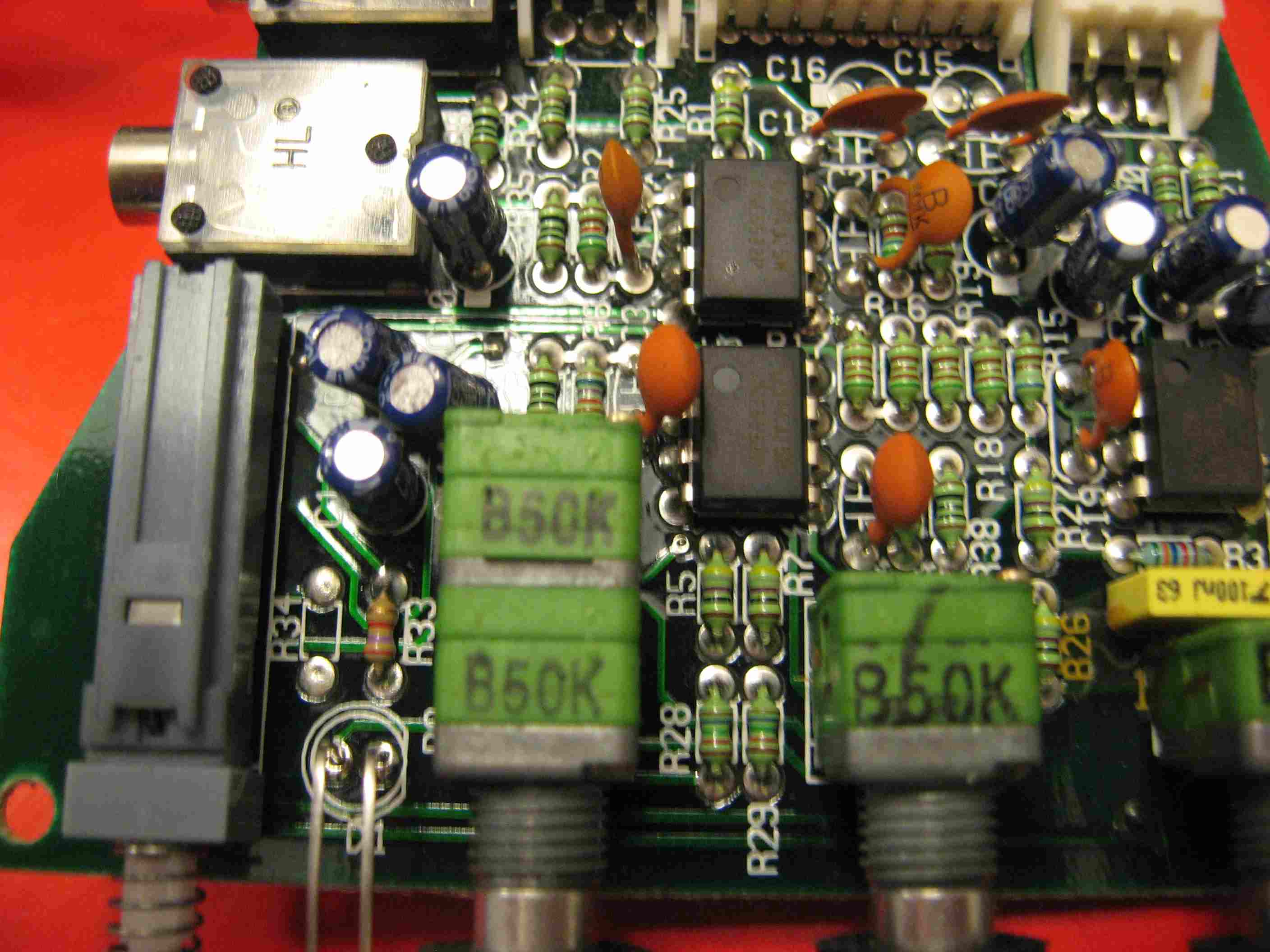
So I opened up the subwoofer (to get to the amp) and saw that there were two resistors that had some problems:
R12 and R26. (680ohm and 47k ohm, respectively).
Note: these first two photos are not my photos- I found them elsewhere. (My Photos are now added at the end of the post, below) They give you a good idea of what has happened though. The R12 picture shows the zip tie. My zip tie was completely melted, and broken through! But, the R12 was still working. My R26 was way worse than shown in the second picture though...

R12 is the gray resistor.
R12 heated up like a bitch in heat, and melted a zip tie that was used on the board for structural support. But, after measuring the resistance with my DMM, 680ohm on the button- so this wasn't the problem. Sure was scorched though...

R26 is the brown resistor.
R26 basically exploded. The shell of the resistor was cracked, fragmented, and the current path was completely blown open.
Well, using my trusty soldering iron, solder, some desoldering braid, and some new resistors from Digikey, I replaced R26.
My speakers work again!!!
Here is a link to some rough schematics that some guy made, if you are interested:
http://www.thompdale.com/bash_amplifier/bash_amp.htm
By the way, I think the original R26 was a 1W resistor, so I replaced it with a 3W lol. I also bought some replacement resistors for R12, just in case it decides to go later.
I hope this helps someone out there. (these two resistors seem to be a common problem with this particular amplifier)
Crappy Photo Guide Tour:
Photo 1: Unopened subwoofer box. The screws you need to remove are circled in red.

Photo 2: Subwoofer box open. Careful now, don't rip it open so fast. Look underneath the board, and disconnect the speaker leads from the board.

Photo 3: Insides of the subwoofer enclosure, with the amp no longer in place.

Photo 4: Entire plate amp assembly.

Photo 5: The new R26 I put in place (47k ohm). Notice its large, manly size. That's because it has a 3W power handling capacity. The old one only had a 1W capacity. Arrows indicate where I had to bend the resistor leads to fit it in the PCB holes")

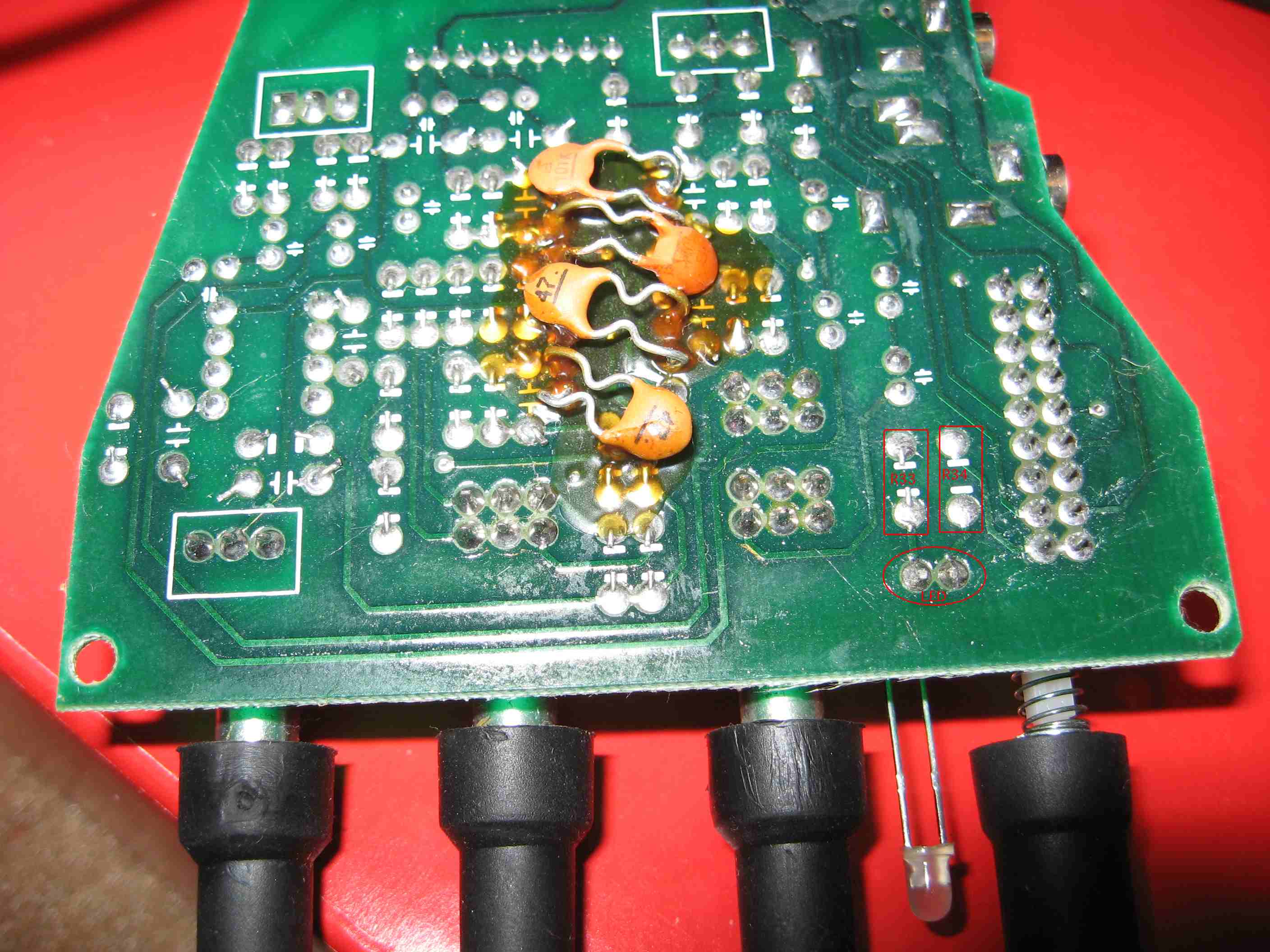
Photo 6: Rear side of the PCB (the side you solder on). Yeah, I used a tad too much solder. no harm done.

Photo 7: Old, destroyed R26 (47k ohm, 1W).

Photo 8: Old R12 (680 ohm) still going strong. Notice the charred PCB? Excessive heat melted the zip-tie that was connected to the board at the red circled hole. The black stuff is from the burning of that plastic zip-tie.

Photo 9: Old fuse, still intact. If only this were the common failure point! lol fucking klipsch....

Photo 10: One of the rows of MOSFETS. Mine are fine, but I think I once read about someone having problems with those, and them fixing it.

Photo 11: The other row of MOSFETS.

I thought I would post about something I fixed last week.
So, while I was at work, my wife needed a power outlet, so she unplugged my Klipsch 4.1 speakers from the surge protector (not the V2.400 version, but the newer revision that Klipsch made right after that. all this is applicable to both though, as all klipsch really changed was the crossover points for the satellites).
Long story short- wasn't muted, so when she plugged it back it- speakers no worky no more.
These aren't the best speakers, but for casual computer music and gaming use, they're great (and I've had them for a pretty long time).
So I opened up the subwoofer (to get to the amp) and saw that there were two resistors that had some problems:
R12 and R26. (680ohm and 47k ohm, respectively).
Note: these first two photos are not my photos- I found them elsewhere. (My Photos are now added at the end of the post, below) They give you a good idea of what has happened though. The R12 picture shows the zip tie. My zip tie was completely melted, and broken through! But, the R12 was still working. My R26 was way worse than shown in the second picture though...

R12 is the gray resistor.
R12 heated up like a bitch in heat, and melted a zip tie that was used on the board for structural support. But, after measuring the resistance with my DMM, 680ohm on the button- so this wasn't the problem. Sure was scorched though...

R26 is the brown resistor.
R26 basically exploded. The shell of the resistor was cracked, fragmented, and the current path was completely blown open.
Well, using my trusty soldering iron, solder, some desoldering braid, and some new resistors from Digikey, I replaced R26.
My speakers work again!!!
Here is a link to some rough schematics that some guy made, if you are interested:
http://www.thompdale.com/bash_amplifier/bash_amp.htm
By the way, I think the original R26 was a 1W resistor, so I replaced it with a 3W lol. I also bought some replacement resistors for R12, just in case it decides to go later.
I hope this helps someone out there. (these two resistors seem to be a common problem with this particular amplifier)
Crappy Photo Guide Tour:
Photo 1: Unopened subwoofer box. The screws you need to remove are circled in red.
Photo 2: Subwoofer box open. Careful now, don't rip it open so fast. Look underneath the board, and disconnect the speaker leads from the board.
Photo 3: Insides of the subwoofer enclosure, with the amp no longer in place.
Photo 4: Entire plate amp assembly.
Photo 5: The new R26 I put in place (47k ohm). Notice its large, manly size. That's because it has a 3W power handling capacity. The old one only had a 1W capacity. Arrows indicate where I had to bend the resistor leads to fit it in the PCB holes
Photo 6: Rear side of the PCB (the side you solder on). Yeah, I used a tad too much solder. no harm done.
Photo 7: Old, destroyed R26 (47k ohm, 1W).
Photo 8: Old R12 (680 ohm) still going strong. Notice the charred PCB? Excessive heat melted the zip-tie that was connected to the board at the red circled hole. The black stuff is from the burning of that plastic zip-tie.
Photo 9: Old fuse, still intact. If only this were the common failure point! lol fucking klipsch....
Photo 10: One of the rows of MOSFETS. Mine are fine, but I think I once read about someone having problems with those, and them fixing it.
Photo 11: The other row of MOSFETS.