Another doozy: battery operated telephone doorbell...

starhawk

[H]F Junkie
Joined
Oct 4, 2004
Messages
8,908
Yep. Starhawk's got another goofy project in his head.

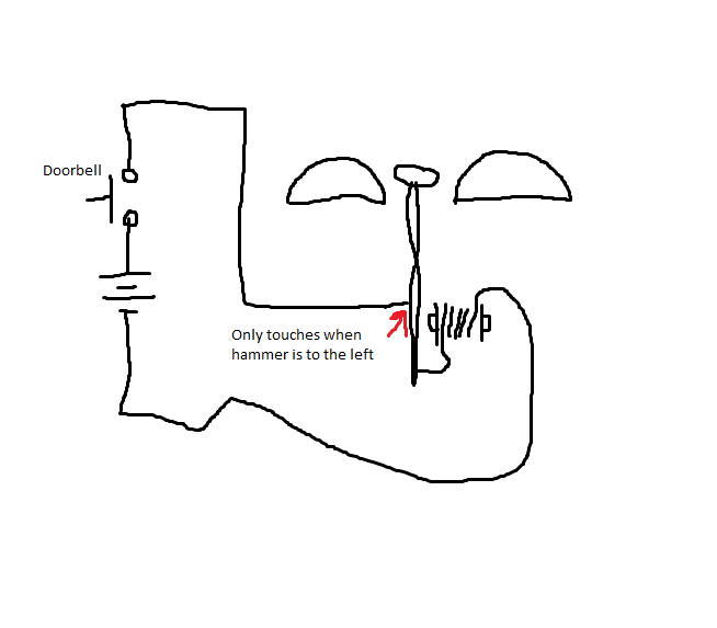
This time I'd like to make a doorbell. I've got an old telephone bell (from a rotary phone, specifically an ITT clone of the Western Bell Model 500). I'd like the mailman (or whomever happens to wander by) to be able to push a button and BRRRRRRRRINNGG!!! It's time to answer the door!

Trouble is, those old bell coils were used to ~90vAC at about 20Hz -- not something easily obtained from a few AA cells. LOL.

I have a bunch of odds and ends and bits of things that I could throw into this. I know I've got at least one 10uF capacitor. I've got a couple resistors of different values (don't recall what the values /are/ tho, at least offhand) and things like that. If I had to I could take some wire and an old screwdriver and make a transformer :eek: although it sure as hell won't be UL listed!

If I absolutely have to buy parts, I can get whatever's in stock at the local Radio Shack on Monday -- but I don't want to spend more than $15 at the absolute most.

I'd like to use a quartet of C cells as the power source. I've got at least 16 (and I think closer to twice that!) of the damn things, all disposable... all a little older but they should still be good. They've never ever been used. (Yes I know about self discharge. They're not from 1985, Doc! :p )

Can this even be done? If so: guide me!
 
The easy way to do it is to hack it so it works like a *really* old-school buzzer. Such a device is a simple DC circuit--the arm which swings between the gongs (that's what those bells are called) alternately closes and opens a circuit which powers an electromagnet which swings the arm. So battery -> button at front door -> coil -> contact -> arm -> battery. At rest, the contact on the arm is closed, and once the arm moves, it breaks the contact. The mailman pushes the button, the coil powers up, the arm moves towards the gong, the contact opens up, the arm (thanks to momentum) keeps going until it hits the gong, then it goes back to the point where the contact closes again, swings back towards the gong, etc.
 
That's actually a little too simple for me...

EDIT: in more detail... there are two bells with the hammer in the middle. I want a circuit which makes the hammer strike one bell and then another -- +v then 0v then -v then 0v then +v then... you get the point. I'd like to do it as simple as possible but mostly electronically.
 
Tweak it just right, and that's exactly what you'll get with the simple circuit I described. The coil will pull the hammer towards one bell, then it will spring back and strike the other (at which point the contact is closed and it gets pulled back towards the first bell).
 
My head's too simple these days to tweak that idea. I can't quite even envision it...

Is there something simple I can build that generates a sine wave, that I can then put through a mosfet and crude transformer to spit at the bell coil?
 
MSPaint to the rescue!
doorbell.png
 
You can still do it--you'll just need to re-wind the coil with fewer turns. You can either do it the Engineering way--calculate or measure the current when it's plugged into the wall, and recalculate the new number of turns, etc--or you can keep adding turns until it's strong enough to pull the hammer back and forth.

An old phone like that probably takes about 10mA (from the research I did), and the minimum ring voltage is 40VAC. The force of the coil is proportional to the number of turns squared, and also proportional to the current squared. Since you'll be supplying much lower voltage, you'll need to reduce the number of turns by a factor of about 5. This will reduce the number of turns, but increase the current, so you end up with a similar strength of pull.
 
Last edited:
Kinda what I'm picturing is a 555 circuit that outputs a sine wave to something like a MOSFET (obviously not an actual MOSFET because it'd fry the transistor quickly when the sinewave dips to -v...) that can handle some higher voltage.

I'll work out the voltage source later.
 
Use a 555 as an astable multivibrator which feeds a power transistor to drive a transformer. An example I found on the web is here:
http://ahmad-muzakki.blogspot.com/2010/03/brakelight-flasher.html
just replace the bulb with a transformer that has a secondary rated between 6 and 12 volts. Hook up the secondary in place of the bulb and run the doorbell off of the primary.
Also, change R1 to 1K and C1 to 1uF. Adjust the pot to give best results - it should give between 14 Hz and 1000 Hz.
 
Yes, that transformer should work. It's rated for 300ma @ 6.3v, which should be 15ma @ 120v, but that's for continuous use. Intermittent use can be much higher. In practice, there will be a lot of variables that come into play for voltage and current, but there's a lot of room for error in this circuit. The voltages are between 40 and 160 volts and current is probably 10-30 ma for the telephone coils. On the other side of the transformer, you'll probably need 2-8 volts and maybe a quarter amp, but this is all approximation. The current pulled by the coil will be the current passed by the transistor. That can be calculated by taking your supply voltage, dividing by the resistor R2, and multiplying by the Hfe (current gain) of the MJE3055 transistor (that's the much more user-friendly TO-220 package of the 2N3055, they're available at RS).
Let's say you're running at 12v (you'll lose 0.7v across the transistor as well). If R2 is 1K and a value for Hfe is 100, then you'll have 11.3 * 100 / 1000 = 1.13 amps.
Of course this assumes Hfe is at its maximum, that there's no voltage sag from the batteries, and neglects the resistance of the transformer. You could run a lower voltage or increase R2 to decrease the current - 9v and a 2k resistor could work. Try starting small on the voltage, say 6v, and working up to 12v if needed. Also, you could buy 4.7K resistors and use that for R2. Start with one and test, and if needed, put another one, two, or three in parallel to increase current through the transistor.
 
OK, I want to run this off 6v, so let me see if I can math correctly today... I'll leave your other values the same.

(6 - 0.7) * 100 / 1000
5.3 * 100 / 1000
530 / 1000
= 0.53a

Also, just FYI, radio shack calls their MJE3055 a "TIP3055"... w/e it's radio shack.

I think I'll use this transformer because radio shack parts aren't known for being rugged anymore -- http://www.radioshack.com/product/i...03732&filterName=Brand&filterValue=RadioShack
It's a lot more expensive tho :(
 
As long as it's not constant use, a small transformer should be fine. Heat is what kills transformers and this will get so little use that it won't ever get hot.
 
That does make sense, actually.

BTW, the first line in your sig is pure gold -- and very wise as well.
 
Back
Top